In this blog, we are going to explain how to use the Levels and Planes Managers in Mastercam to improve your programming efficiency when using this CAD/CAM software.
What is a Level?
In simple terms, a level is a layer on which you can put specific CAD information. Levels can be turned ON or OFF in any sequence or combination. When working with a large number of parts, for instance a vice, a stock model, and a part file, it becomes very handy to have these items hidden and shown when needed. When using only a single level for all geometry, it can become quite overwhelming in the Mastercam window, and this is why the Levels Manager is important.
The Levels Manager explained:
Mastercam files can contain several levels of data for the wireframe, solids, surfaces, drafting and toolpaths of a particular part.
What is the Levels Manager?
The Levels Manager is a tool that shows the current levels in your Mastercam file. It allows you to create, select, hide or show levels. It also allows you to set the active level for your part. The active level will be allocated to any new wireframe or part files that are created.

The Levels Toolbar at top of the Manager in Figure 1 shows the following features:

The Planes Manager explained:
If your Mastercam part file consists of various planes within its geometry, it can be beneficial to have machining planes set up to allow machining from different angles. Mastercam addresses this through the Planes function and Planes Manager.
In Mastercam, planes can be used to do any drawing or toolpath design. When creating a wireframe to define an avoidance/inclusive region, for example, it needs to be on a plane that will sync with the direction that the tool is coming from. This will typically also be used in 3+2 multi-axis toolpaths. Figure 2 and Figure 3 show wireframes and toolpaths on different planes.


What is the Planes Manager?
The Planes Manager allows you to select, edit, create and manage planes within Mastercam.

The Planes Toolbar at the top of the Manager in Figure 4, shows the following features:

What is the meaning of “G, WCS, C and T” in Mastercam?
In Figure 4, we can see the different columns for different planes, we will learn about G, WCS, C and T below:
- G-view or Graphic-view refers to the current viewing angle in the graphics window. For example: if you are in an isometric view your Gview = Isometric.
- WCS – Work Coordinate System, you can choose to align the coordinate system to any plane you wish. As a result, your XY plane will then be mapped to that view. The origin of the view becomes your new (0, 0, 0) point. The view becomes the Top Plane in the new WCS you have created.
- C – Construction plane, indicates that the geometry created will be placed on the plane where the “C” is checked in the column.
- T – Tool plane (T-plane), is only used when creating toolpaths. The tool plane determines the orientation of the tool.
4th Axis rotary indexing toolpaths using planes
In Mastercam, you can create and use planes to index your toolpath on the angled faces of your model. Figure 7 shows the simulation of a 4th Axis indexing operation with counterboring and drilling. The following steps will guide you through the process:
1. Go to the Planes Manager (see Figure 4)
2. Set your specific plane as Active (i.e., Front, Right)
3. Go to the Toolpath Manager (see Figure 5):
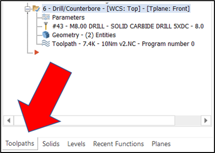
4. Click on “Parameters” under your specific tool operation and then on the feature tree on the left, click on “Planes”, see Figure 6.

5. You then need to select your WCS, T-plane and C-plane (Figure 6). For this example, we set the WCS to the Top plane, and keep the T-plane and C-plane set on the front plane. This will create an A-axis move which will be posted in the NC code.
6. Green check out and verify your model to enter the simulation as seen in Figure 7.

How to use Viewsheets
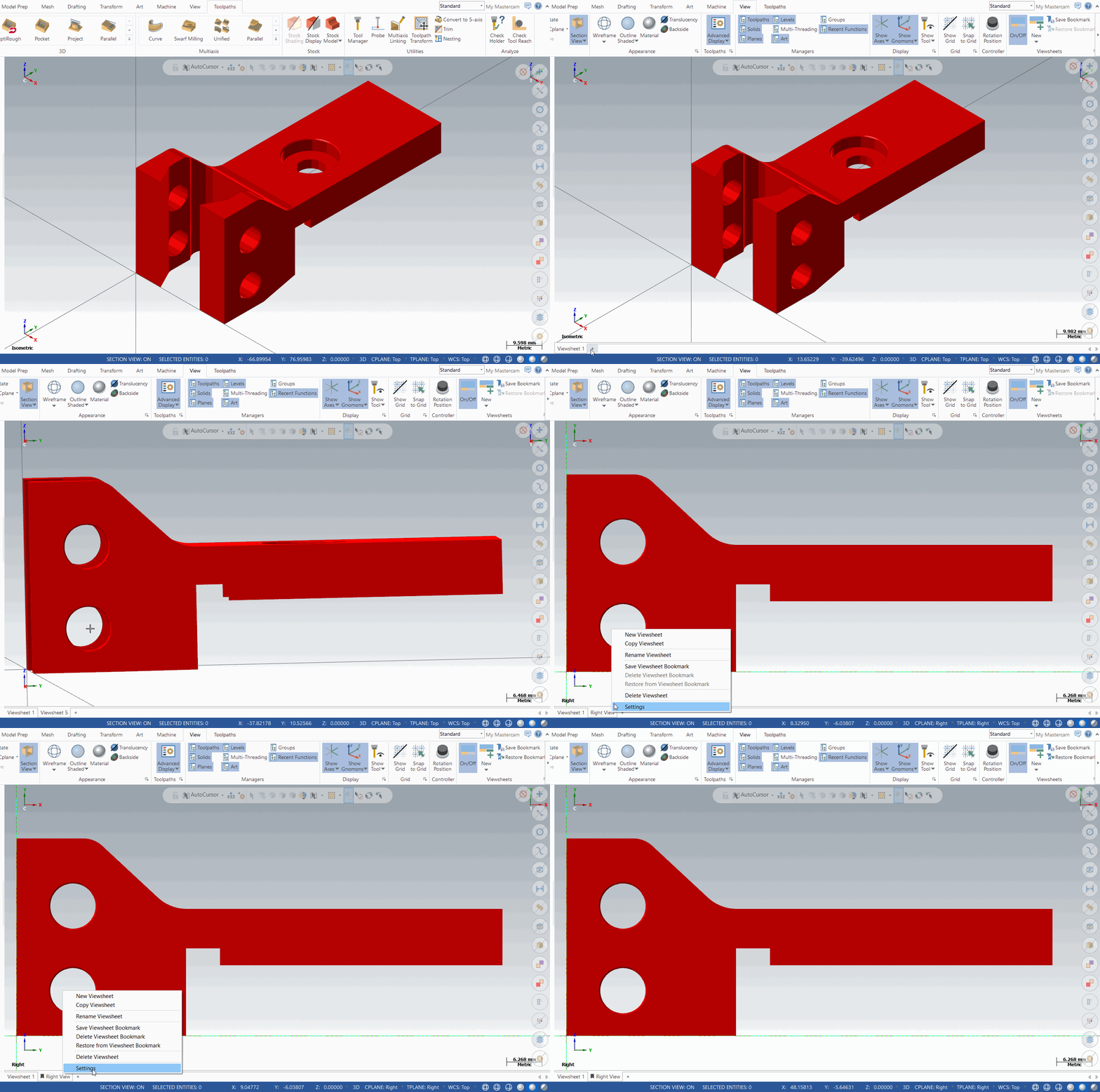
Planes can also be used to orientate the part into a view that correlates with the geometry of the part. That way you can keep an eye on the accuracy of your design or toolpath. There is a special feature called “Viewsheets” that can be used to set up multiple different standard views of your part, for quick reference during design and toolpath creation. You can also create a bookmark for each viewsheet that will store the settings for each view of the part. When you save your part file Mastercam will save all the viewsheet settings along with the part. The GIF below demonstrates step-by-step how to turn ON, create, rename, bookmark, and access the settings of a viewsheet. You can also follow these steps:
- Click on the “View” Tab, go to the “Viewsheets” Tab Group and toggle viewsheets “ON”. You will then see a tab labelled “Viewsheet 1” at the bottom left of your graphics window, under the gnomon.
- Click on the “+” to add more viewsheets to your part file. This sheet should by default be labelled “Viewsheet 2”. Note: In this example, the viewsheet is assigned number 5 because I added 3 viewsheets and deleted them prior to recording. Mastercam numbers the viewsheets in sequential order even after deleting them. This gives the user an idea of how many viewsheets were created in this specific part file.
- Right-click anywhere on the grey shadow in the graphics window. From the menu, choose the Top (WCS), Front (WCS), Right (WCS) or Isometric (WCS) view. In this example, we chose Right (WCS). Note: This is the view that you want the bookmark to save for this specific viewsheet.
- Right-click on “Viewsheet 2” and choose “Rename” from the menu. Rename the viewsheet to the view you chose in step 3 or to your preference. Right-click again on the new viewsheet (e.g. Right view) and click “Save Viewsheet Bookmark”, this will save your view and viewsheet properties. Now you can switch between viewsheets and see that your bookmarked viewsheet has saved the orientation of your part.
- Right-click on the new viewsheet and click on “Settings” from the menu. This will bring up the viewsheet properties box. Here you may edit the properties of this specific viewsheet and green check out to save the settings to it. Note: The viewsheet settings can be customized for each viewsheet in the part file.
This blog on how to improve your programming efficiency by using the Levels and Planes Managers in Mastercam, is part of the MECAD Mastercam Interface Series. Follow us on LinkedIn and stay up to date with the latest blogs in this series as well as webinars and news.
If you need Mastercam support, please contact the MECAD Manufacturing Support team.