
1. What is Mastercam probing
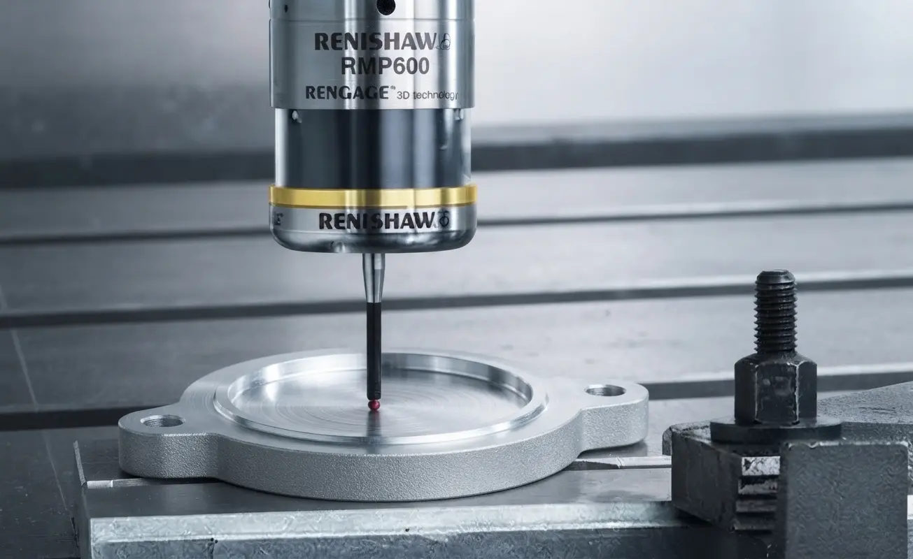
Probing is the use of a touch probe on a CNC machine to automatically measure a workpiece, tool, or machine position. Instead of relying on manual measurements and operator input, the probe can physically touch the part and send the measured information back to the CNC control.
In a typical machining environment, probing can be used to locate a workpiece, find edges and surfaces, measure features, reset work offsets, check dimensions, and verify that a part is positioned correctly before or during machining.
Mastercam allows these probing movements to be programmed directly alongside your machining operations. This means the probing process can become part of the same CAM workflow used to create the rest of the CNC program.
The result is a more automated setup and measurement process, helping reduce manual intervention and making it easier to repeat the same process across multiple parts.
2. Where do you find the probing operations
Once the Mastercam Probing add-on is installed and activated, it adds a dedicated Mastercam Probing tab to the Mastercam ribbon. This provides access to the probing-specific operations within the same Mastercam environment used for programming your machining operations.
Within the Mastercam Probing tab, you will find a range of preset probing cycles designed for different measurement tasks. Rather than manually creating each individual probe movement, you can select the appropriate cycle and configure it.
The available cycles include operations for measuring features such asangles, widths, rectangles, diameters, corners and points.
These probing operations can be used for two main purposes:
- Workpiece alignment and offset resetting – locating the workpiece and updating work offsets or datums based on the measured position.
- Workpiece inspection – measuring features on the workpiece to verify their size, position, or other dimensional requirements.
This makes probing an integrated part of the Mastercam programming workflow, allowing probing operations to be programmed alongside your normal machining operations.
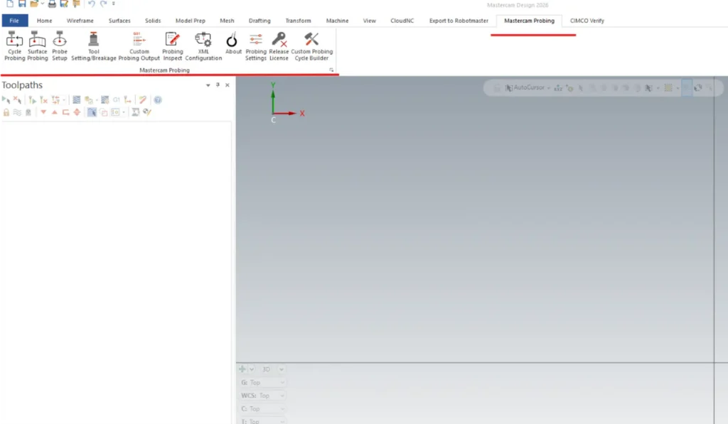
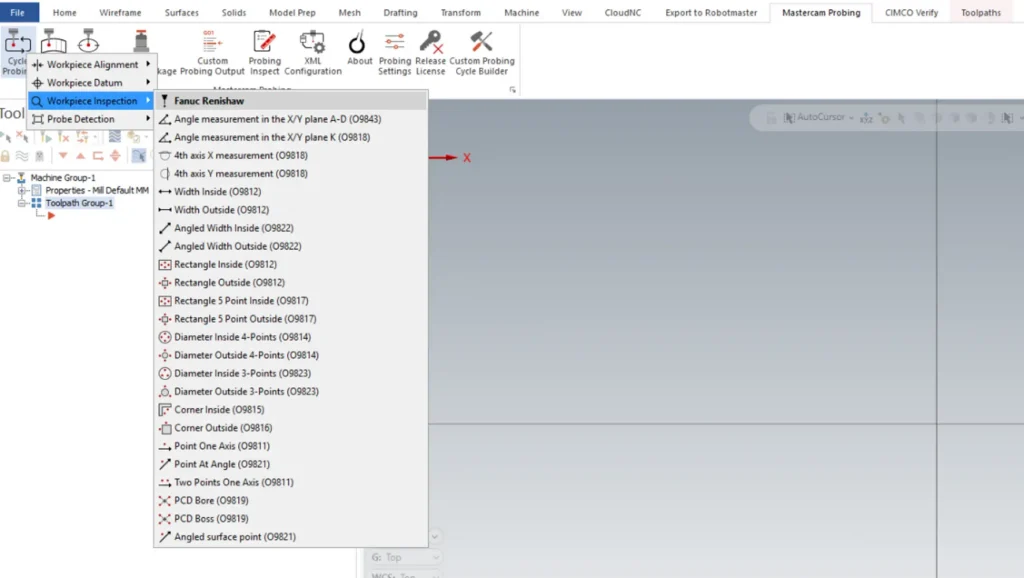
Used either for resetting workpiece offsets or inspecting the workpiece.
3. Setting up the probe/tool
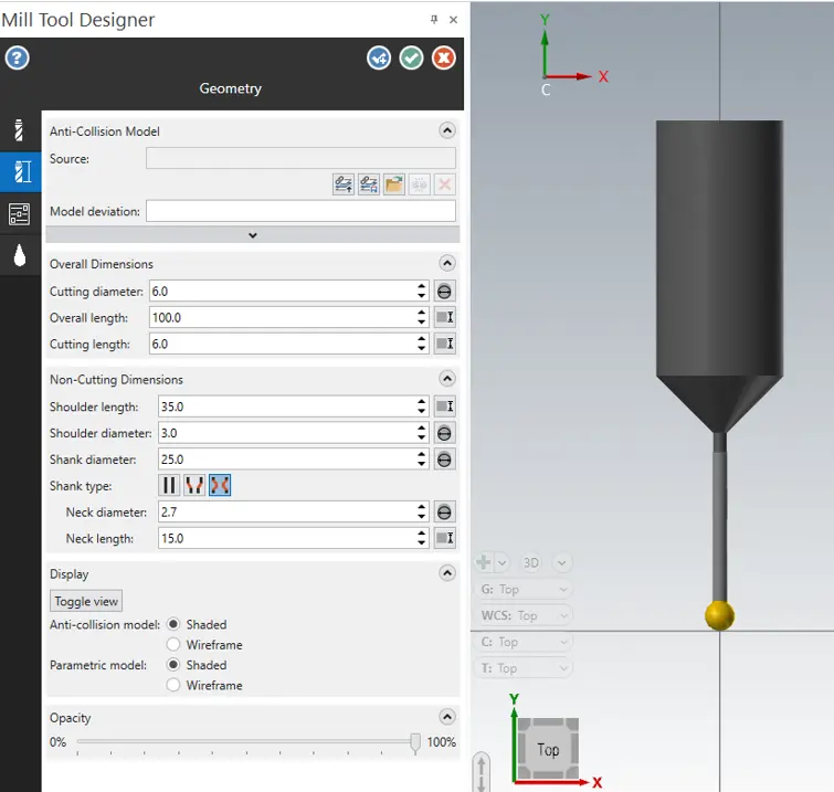
Before creating a probing operation, the probe needs to be defined in the Mastercam tool list. This allows Mastercam to understand the size and position of the probe when calculating and simulating the probing movements.
A simple way to do this is to create a lollipop mill with the same diameter as the probe’s stylus ball. For many probing applications, this provides enough geometry for Mastercam to correctly represent the probe during programming and simulation.
For example, if the probe has a 6 mm diameter stylus ball, a 6 mm lollipop mill can be created and used as the probe tool.
If more accurate machine simulation is required, the probe and holder can also be modelled with their actual geometry. This allows the complete probe assembly to be represented in the simulation, including the holder and any other components that could potentially interfere with the workpiece or fixtures.
For a basic probing setup, however, using a lollipop mill matching the probe geometry is a simple and effective way to get started.
4. Creating your first probing operation
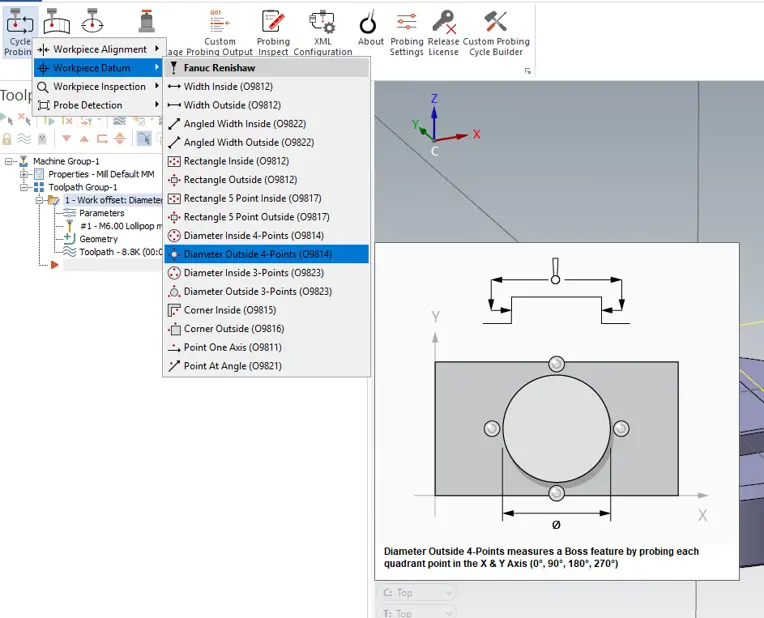
For our first probing operation, we will use the Workpiece Datum (Offset) cycle. This cycle can be used to locate the workpiece and reset the selected work offset, such as G54 or G55, to the actual measured position of the part.
Before running the probing cycle, the work offset needs to be set correctly in Mastercam and approximately on the machine. This initial offset can be set manually by the machine operator. It does not need to be perfectly accurate, but it needs to be close enough that the probe can safely reach the expected location of the workpiece.
The Workpiece Datum cycle will then probe the workpiece and use the measured location to update the selected work offset to the exact position of the part.
This is particularly useful when setting up multiple workpieces. Even when a fixture is used, there can be small differences in the position of each workpiece. Rather than relying on the operator to manually set every offset to exactly the same location, the probing cycle can automatically find the actual position of each part and update the work offset accordingly.
One important consideration is that the initial offset must be close enough for the probing cycle to operate safely. The probe will move based on the position programmed in Mastercam, so if the machine’s initial offset is significantly different from the expected position, there is a risk of the probe contacting the workpiece, fixture, or another component unexpectedly.
When programming the operation, sufficient clearance and safe approach positions should therefore be considered. The initial offset is only intended to get the probe into the correct area; the probing cycle then takes over and accurately establishes the final work offset.
Once the cycle has completed successfully, the selected work offset on the machine will be updated to match the measured position of the workpiece. This provides a repeatable way of establishing accurate datums and is especially valuable when machining multiple workpieces where the exact placement cannot be guaranteed each time.
5. Selecting the geometry and understanding the probing parameters
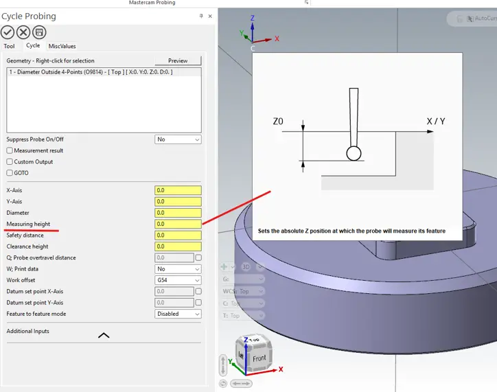

Once the probing operation has been selected, the next step is to define the geometry that the probe will measure and configure the required parameters.
The parameters available will depend on the probing cycle selected. Different cycles require different information depending on the feature being measured. For this example, we will use a 4-Point probing cycle.
When using the 4-Point cycle, there are several important parameters to understand:
- X and Y – These values define the centre position of the feature being probed in the X and Y axes.
- Diameter – This defines the expected diameter of the feature being measured.
- Measurement Height – This defines the Z height at which the probe will make contact with the workpiece.
- Safety Distance – This is the distance away from the workpiece where the probe moves down at the programmed feed rate before moving towards the part to make contact.
- Clearance Height – This defines the height the probe moves up to before travelling to the next point being measured. This allows the probe to safely move between measurement locations.
As the required values are entered, Mastercam will begin displaying the actual probing toolpath in the graphics window. This is particularly useful because you can immediately see how the probe is going to approach and measure the feature.
Another useful feature when working with the probing parameters is the parameter tooltips. By hovering over a selection field, Mastercam displays a small information box containing an illustration and description of what the parameter represents. This makes it easier to understand what each parameter controls without having to refer to separate documentation. As you work with different probing cycles, the parameters will change depending on what is being measured. Understanding these parameters is therefore important for both safe probe movement and accurate measurement.
6. Verifying the probing moves in Mastercam
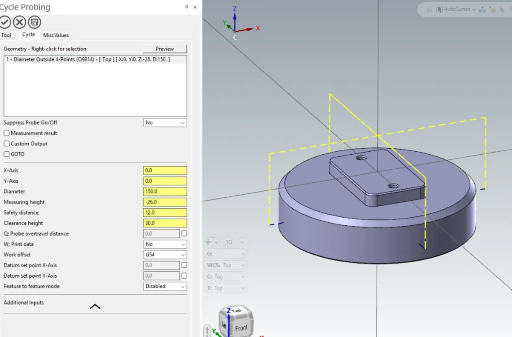
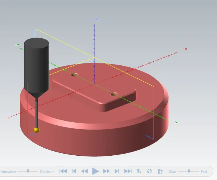
This is the view while editing the parameters. You can adjust the values and actively see the toolpath update.
It is easy and user-friendly to verify probing movements in Mastercam. Probing operations work much like standard toolpaths, meaning that familiar features such as Backplot and Verify can be used to check the programmed movements.
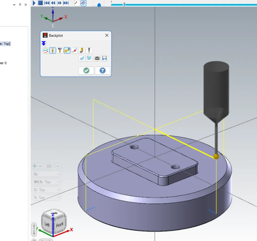
Using Backplot, you can step through the probing operation and see exactly how the probe will move around the workpiece. This allows you to check the approach and retract movements before posting the program.
The Verify function can also be used to simulate the probing operation. This provides a visual representation of the probe movements and makes it easier to identify any potential issues before running the program on the machine.
This is particularly useful for checking that:
- The probe is approaching the correct feature.
- The probe is moving to the correct measurement height.
- The safety distance is appropriate.
- The clearance height is high enough when moving between measurement points.
- The probe is not going to interfere with the workpiece or fixture.
Being able to verify probing movements in the same way as normal toolpaths makes the process simple, visual, and user-friendly. It also provides an additional opportunity to identify potential problems before the program reaches the machine.
7. Posting the probing code
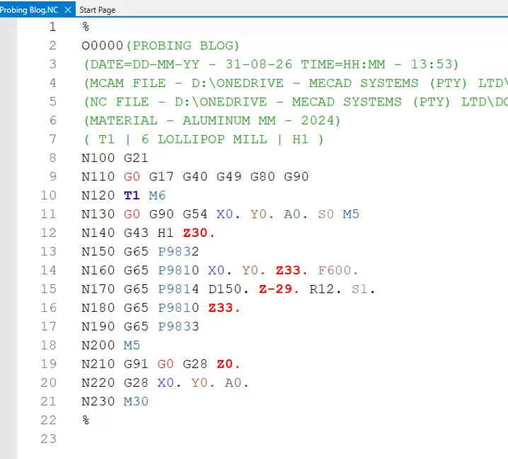
As shown in the image, the probing code is output in much the same way as a normal machining toolpath. The probing movements are included directly in the NC program and can be posted alongside the rest of the machining operations.
The key to the probing process is the use of the probing cycles already built into the machine controller. For example, when using a Renishaw probing system, Mastercam outputs the appropriate commands and parameters required by the Renishaw cycles.
These cycles are stored within the machine controller and are responsible for carrying out the actual probing routine. Mastercam provides the controller with the required information, including the P commands, which tell the probing cycle what measurement or action needs to be performed.
This means that Mastercam is primarily being used to program and define the probing operation, while the machine controller’s built-in probing cycles handle the actual measurement process when the program is run. As with any CNC program, it is important to make sure that the correct post processor and machine-specific probing configuration are being used. The output must match the probing system and controller on the machine for the probing cycles to operate correctly.