In this article, I will be discussing the steps and procedures of taking NC code from a DXF to a CAD model using Cimco and Mastercam. Take note that these steps are only intended for Lathe parts, but can in certain scenarios also be used in milling.
Now, this has happened to most companies in some way or another. You generated g-code and machined a part, just to find out your CAD model got corrupted or lost. Or maybe the part is so old that the only thing you have of it is old manually programmed g-code that needs to be reverse-engineered.
Now, this might sound easy. I mean it’s just a lathe part, but after only 2 steps in you realize, tip compensation is a tough cookie and even though offsetting everything by the tip radius does create parts, it would mostly be scrapped parts.
But fear not as this is possible and after reading this article, you’ll be well on your way trying to see if reverse engineering couldn’t save other parts of your life.
Okay first things first, the things you will have to know for this to work is the tool radius of the tool/tools that was used, as well as the direction in which they moved.
The tool radius is important as we need to know how much the geometry needs to be offset to and the direction is important as we need to know in what direction to offset the geometry to. Now before I confuse you too much let’s go to the first step.
Converting the NC code to a DXF
The software that I’m going to use, and that is highly underrated, is Cimco. Now take note that this cannot be done with the Cimco lite version you get with Mastercam, but you’ll need the Cimco Edit version that will allow you to backplot NC codes.
Once you have got Cimco Edit open you would then go and open up your NC code by going to File, Open.

After that, I will navigate to my Backplot tab.

Once you are in your Backplot tab, you have to make sure that your File type is set to ISO Turning. This might be true for most manually programmed code as they are mostly FANUC base, but there is another option available like Haas Turning, Mazak ISO Turning, Okuma Turning, Siemens 800 and 840D turning, etc.
Next, I am going to click on the Backplot Window button.

This would give me a window with my NC code on the one side and the code in backplot form on the other.

What could sometimes happen is that your code can be backplotted vertically along the z-axis. To change your view to D+Z+ orientation, click on the View From Tool in the View section.

You can now pace through your code using your arrow button and see how the position of the blue marker changes as it represents the motion the tool would take.
To save this to a DXF file, what you want to do is to click on the Export as DXF button in the Other section

We can then import this DXF file into Mastercam and get the following result.

Now here we have all the feed movements of the tools marked in green and well as the rapid movements marked in red. Cimco would also save each tool-offset combination on a level. For this example, we have the following levels:

What we want to do next, is to delete all the geometry except for the final cuts. I change the colour to blue for clarity.

This is the geometry that we will manipulate to get the outer boundary of your original CAD part. Now before we go any further, we should first look at tooltip compensation and how the tool is compensated when turning a part. There are 9 ways a tool can be compensated when preforming turning operations (There can be more but for simplicity sake let’s stick to 9):

Now I know, it is pretty terrifying but give me a moment to explain it and…. hopefully, this will make sense.
The compensation used in the NC code is number 3. Let’s have a closer look at it:

Do you see that red plus sign on the figure above? That point follows the line that we got from the DXF. We can see that the red plus sign matches the front edge and on the bottom of the insert. Now what this means or what we can assume is that when the tool is moving in a horizontal line or a vertical line, there will be no compensation.


The challenge comes in when the tool moves in any other direction like on an arc or angled path.
To solve for these cases what we need to do first is to offset the final sketch that we got for the DXF by the tool nose radius (0.8mm) downwards:

Now, this is where it gets interesting. After we have done that we have to Translate, Transform all the arc and angled edge by the tool nose radius in the opposite direction of the tool motion.

For this part, it would usually be Y in the positive direction and X in the positive direction because the tool is moving in a negative direction.
After we have transformed all the required geometry, we will then trim and link all the vertical and horizontal line of the original DXF file.

For clarity here are all the steps on one screen:

The next step would be to take care of the cutoff operations. The insert that was used for the cutoff operation had a width of 4mm and was set up the same as the roughing and finishing tool (Number 3 in the compensation diagram). This means that we should offset the line representing the back of the part by 4mm.

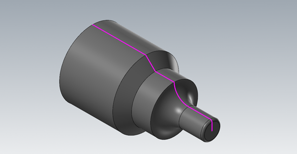
This will give us the finished part:
If you want more information on reverse engineering, NC code or how to get the most out of Mastercam and Cimco to take your business to the next level, please contact us at MECAD Manufacturing.