When working with lathes, one of the biggest problem customers face when they receive new jobs is if a job requires you to cut Rope Thread. This might not only be just Rope Thread but any custom thread with a thread profile.
In the past, rope thread had to be programmed by hand, amounting to a lot of calculation and timely work. At MECAD Manufacturing we tried to solve this problem.
With the release of Mastercam 2021, I am glad to announce that this will no longer be a problem since the new release comes with a new custom thread toolpath!
In this article, I will show you how easy Mastercam has made it to program custom thread toolpaths in Mastercam 2021.
Setting up the thread profile could be done either with a wireframe chain or building it in the toolpath as shown below:

For this example, let’s say we have the following thread profile:

To start this toolpath, and after adding our preferred machine, we should first define stock, as stock is needed before we can create a Custom Thread toolpath. I have defined a stock with a diameter of 25mm and a length of 100mm, which will ensure that our profile is within the stock.

Next, let’s go to lathe toolpaths and expand the gallery to find the custom thread toolpath.

Once we click on the toolpath, we will be greeted with the new format that Mastercam is starting to roll out. On the first page of the toolpath we are asked to define our tool.
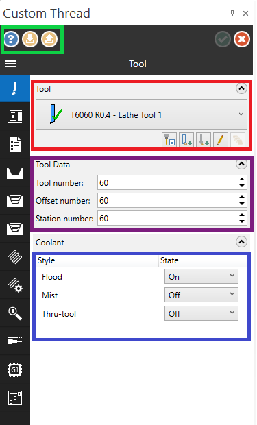
There are quite a few things that we can set on the first page. Starting in the top left corner (marked in green) we have the Help button. When clicking on the help button it doesn’t take us to the usual help files, as seen in the previous versions, but will open a file in the browser page.
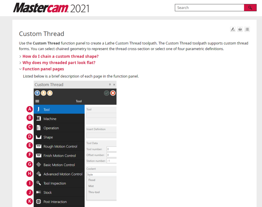
Take note that this doesn’t require you to have internet access as it only uses the browser to display files that are saved on your hard drive.
Next to the help button, we have the Save Defaults and Load Defaults buttons that would allow us to save and load all the parameters set in the toolpaths to enable us to quickly load and save custom thread we frequently use, speeding up our process.
Next, we must define the tool that we are going to use. This can be done in the area marked in red. As usual, this can be done by either selecting a library tool, creating a new tool, importing 3D lathe tooling or editing existing tools.
We can then set the Tool number, Offset number, Station number and what coolant codes should be posted out in the purple and blue marked areas.
Next, we click on the machine Icon to go to the Machine setup page.
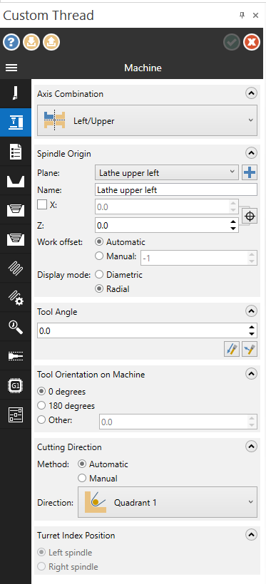
Here we can set the spindle and turret setup being used, as well as the Tool Orientation, Angle and Cutting Direction.
Next, let’s go to the operations page.

Here we can set where the Home Position of our machine is. We can also set an Approach and Retract reference point if we would need those. We can add a comment for our operator as well as force a tool change after the operation.
Then, we have to define the shape of our thread.

For this example, I’m going to set my Shape Type to Chain and then click on the cursor button (marked in red) to select the chain.

I’m then going to make sure that my operation is set to an OD thread and specify the pitch of my thread to be 13.1mm.
Next, we are going to set the parameter for the Rough Motion Control.
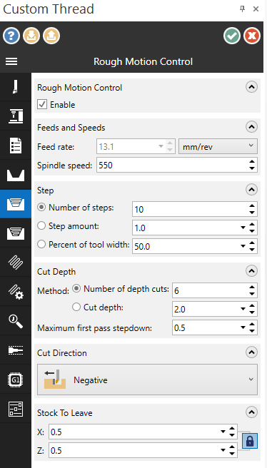
What we can set on this page is whether we would like to do a rough cycle. This means that if you would like to do a rough cycle with one tool and finishing with another, you can create two toolpaths and then switch on the appropriate cycle.
You can then specify your spindle speed, but take note that the feed rate is fixed to the pitch of your thread. Next, we can set the steps (the step along with the stock material) either by a number of steps, step amount or percentage of tool width. After that, we can specify the Cut Depth (cutting into the material) also as either a set number of cut or a specific depth of cut.
Lastly, we can specify the cut Direction to Positive, Negative, Bi-directional alternating, Bi-directional Positive First or Bi-directional Negative First and the amount of stock we want to leave for the finishing cut.
Next, let’s move on to the Finish Motion Control.

Here we can also specify if we want a finishing cut to happen. We can set our Spindle speed with the Feed rate fixed. The step, in this case, is a distance along the Z-axis giving equal 0.2mm steps. The number and depth of finish cuts could also be specified if necessary.
Lastly, the Cut Direction could be set to Positive, Negative or Bi-Directional Alternating and we have the option to leave stock.
The next important page is the Basic Motion Control.
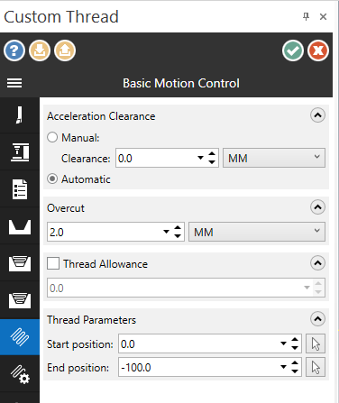
This page is important as we have now specified everything, but Mastercam still does not know where this thread should start and end. This can be set under the Thread Parameter. With this set, we can also specify our Acceleration Clearance or just leave it on Automatic.
After specifying all these parameters, we can click on the green check in the top right corner and Mastercam will generate the following toolpath.
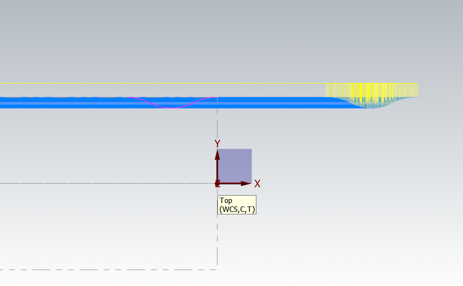
Take note that I’m still working on the Beta2 version of Mastercam 2021 and that the stock does not yet update with the toolpath as normal threads would. To see the proper outcome of this toolpath it should be Verify, as Backplot would only show the tool moving across the material.
Before we verify the toolpath we show, first switch the simulator options to True Thread mode. Without this, our rope thread would look a little flat. The reason why this is not always set is that Mastercam’s stock preview functions only show the first and last threads to speed processing time during screen display.
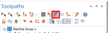
To switch True Thread mode on we first must go to the simulator options marked in red below:
Then to the Data tab and then click on the True Thread mode checkbox.

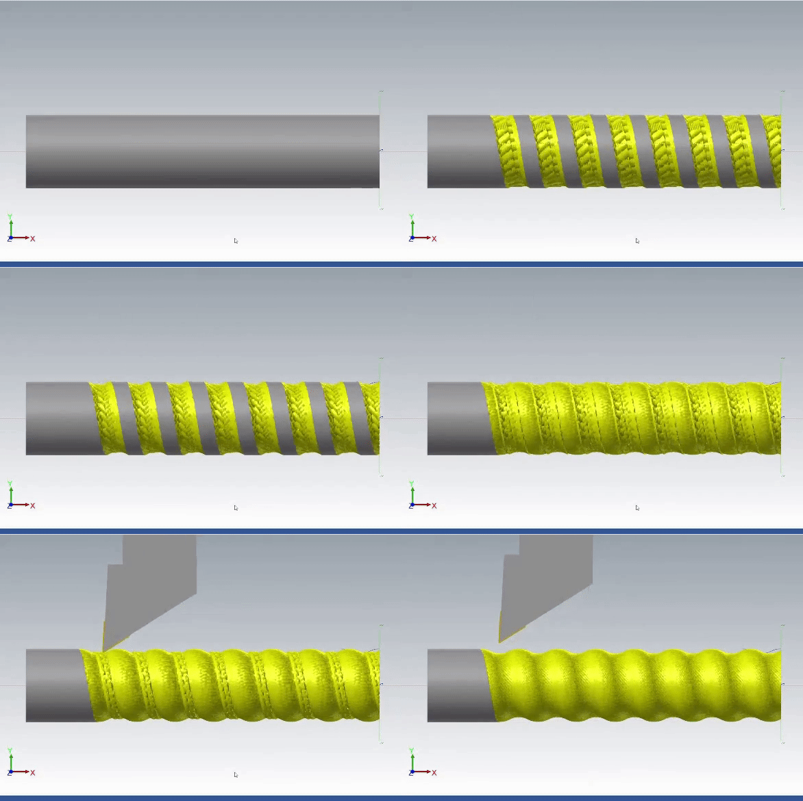
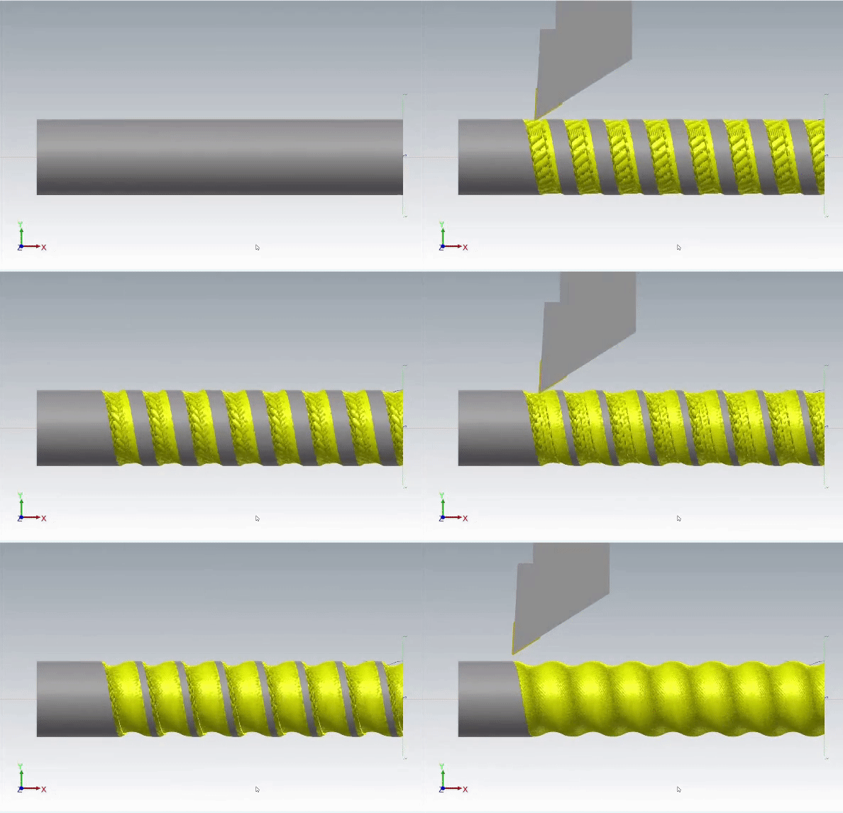
After green checking and going into Mastercam’s Verify, we will see the following results:
The first is Custom Thread toolpath with a Di-Alternating Finish:
The second is the same toolpath with a Negative Finish:
Lastly, if we would take a look at the code of this toolpath, we would see that the standard post-processor uses a G32 cycle to turn the threads.

With the new addition of the Custom Thread toolpath to Mastercam 2021, we are very excited to see how you could use this and other toolpaths in your shop to increase production and save time. For more information on Custom Thread turning please contact MECAD Manufacturing or if you require support please contact mcsupport@mecad.co.za .