An aggregate head, also known as an angled head, lets the machine drive a tool at an angle to the spindle axis.
In Mastercam, you need a machine definition and a control definition that includes the head. You also need a post that knows how to output it for your control.
This blog covers that setup and how toolpaths behave with linking and Z clearance.
The same workflow applies to a VMC or an HMC. The figures use a VMC spindle name.
Environment used: Mill 4-axis VMC MM, GENERIC FANUC post.
Applies to: 3-axis and 4-axis machines.
1. Post and Control Definition
- Pick a post that supports an aggregate head for your control.
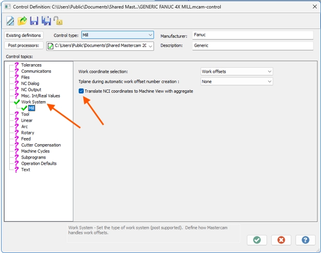
(In this example, I used Mill 4-axis VMC MM, GENERIC FANUC. Yours may differ.) - Open the control definition.
- Under Work System, enable Translate NCI coordinates to Machine View with aggregate.
2. Machine Definition: Add the Aggregate Component
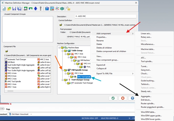
- Open the machine definition.
- Expand the Mill Spindle Group fully.
(Orange arrow.) - Right-click VMC Tool Spindle.
(Turquoise arrow.) - Hover over Add components.
(Red arrow.) - Click Aggregate…
(Black arrow.)
3. Stations and Head Orientation
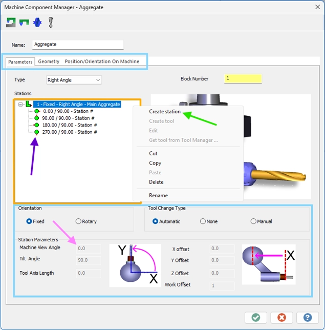
- In the new window, right-click in the Stations area.
(Orange box.) - Click Create station.
(Green arrow.) - A new station appears in the list.
(Orange box.)
Each station represents a distinct logical orientation of the aggregate.
- Select a station and edit its parameters in the property area.
(Light blue boxes.)
Example: four stations with Machine View Angle incremented by 90° for each.
(Pink arrow.)
- Use the green and red axis/orientation indicators to confirm how the head is oriented in the graphics.
(Purple arrow.) - Green-check through the dialogs.
If you are prompted to save the machine definition, choose Yes.
4. Toolpaths: Assign the Angled Head to a Tool
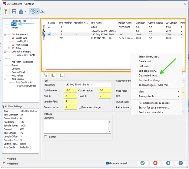
- In your toolpath, select the Tool tab.
(Light blue arrow.) - Right-click in the tool list area.
(Orange highlight.) - Choose Get angled head…
(Green arrow.)
5. Matching Head to Planes
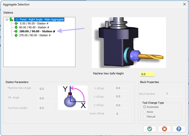
The Aggregate Selection window will open.
If WCS, Cplane, and Tplane were already set for the toolpath, the station that matches those planes is emphasised or pre-highlighted.
Example:
| Plane | Setting |
|---|---|
| WCS | Top |
| Cplane | Right |
| Tplane | Right |
6. Create or Select a Tool for That Station
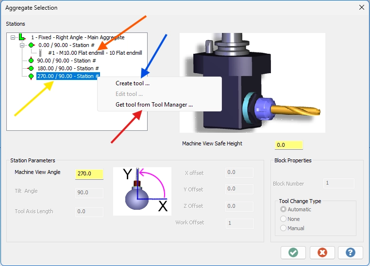
- Right-click the required head/station.
(Yellow arrow.) - Choose one of the following:
- Create a new tool.
(Blue arrow.) - Open Tool Manager and pick a tool from a library.
(Red arrow.)
- Create a new tool.
- After selection, the tool appears under that head/station in the tree.
(Orange arrow.) - Green-check to close.
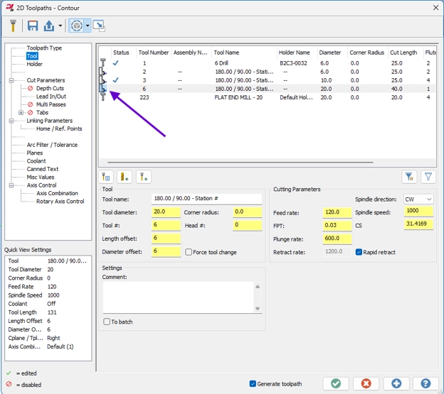
The new tool shows an aggregate/angled-head style icon in the tool list.
(Purple arrow.)
7. Linking and Fixture Z
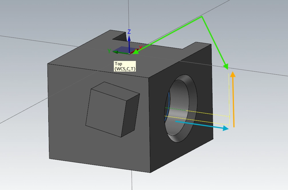
Changing Linking Parameters moves clearance along the tilted tool axis. This is the transformed Z for that head, not the machine’s original vertical Z.
(Blue arrow.)
After retracting along the tilted tool Z axis, the posted code brings the tool to the original Z = 0 plane for the active offset, such as G54 or G55.
(Orange and green arrows.)
Watch for crashes: the danger is travelling along the Z0 plane. This means the machine moves in X and Y with Z held at 0 in the active offset.
The tool could sweep through the part, clamps, or the table, depending on your active offset’s Z0 height.
Linking only helps along the tilted tool axis. It does not prove that the XY path is safe on the original Z0 plane.
8. Extended Linking vs Fixture Z and Between-Toolpath Rapids
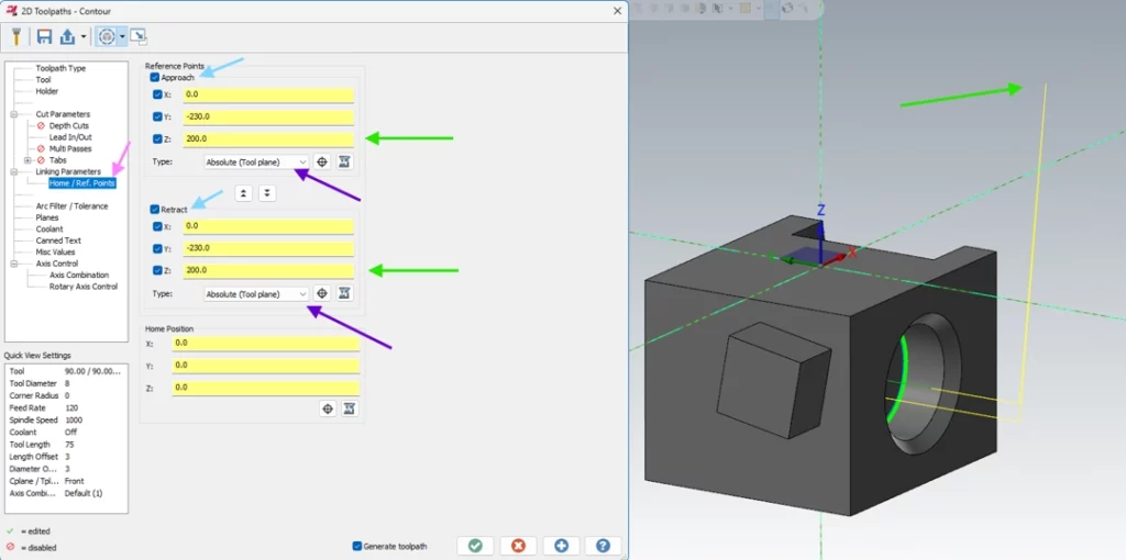
For your toolpath to clear the part and/or fixtures, go to Home/Ref. Points in your toolpath.
(Pink arrow.)
- Switch Reference Points, Approach, and Retract to active.
(Light blue arrow.) - Change the Reference Point Type to the setting that provides a rapid toolpath to clear the job and features.
(Purple arrow.)
Depending on what machine you have loaded and the model geometry, you will have to change the Reference Point Type.
Test different reference point types to find the best movement.
You can now set your X, Y, and Z positions for Approach and Retract. Use these together with the selected type to find the best movement.
Looking at the Z value, you can see that the tool will retract to 200 mm above the active offset, such as G54 or G55, before moving to the next toolpath.
(Green arrows.)
You must confirm that the posted code for the Reference Point rapids is safe to run.