Mastercam drafting is used to add notes and dimensions to solids and wireframe entities. Drafting notes can be used to create dimensioned drawings or as a reference for any user that opens the Mastercam file. In this blog, we will discuss adding notes to a 3D model, and then how to create a technical drawing of the part.
Drafting Tools

Under the drafting tab in Mastercam, tools for dimensioning and annotations can be found. The Smart Dimension tool creates multiple types of dimensions and will switch between them depending on the geometry selected. If the Smart Dimension tool is not giving the desired output, then specific tools like vertical or angular can be used to add the required dimensions. The Note tool is used for creating text that can be altered after creating it, unlike the Text tool in the wireframe tab which creates actual lines and arcs. This tool is useful for creating reference notes on parts.

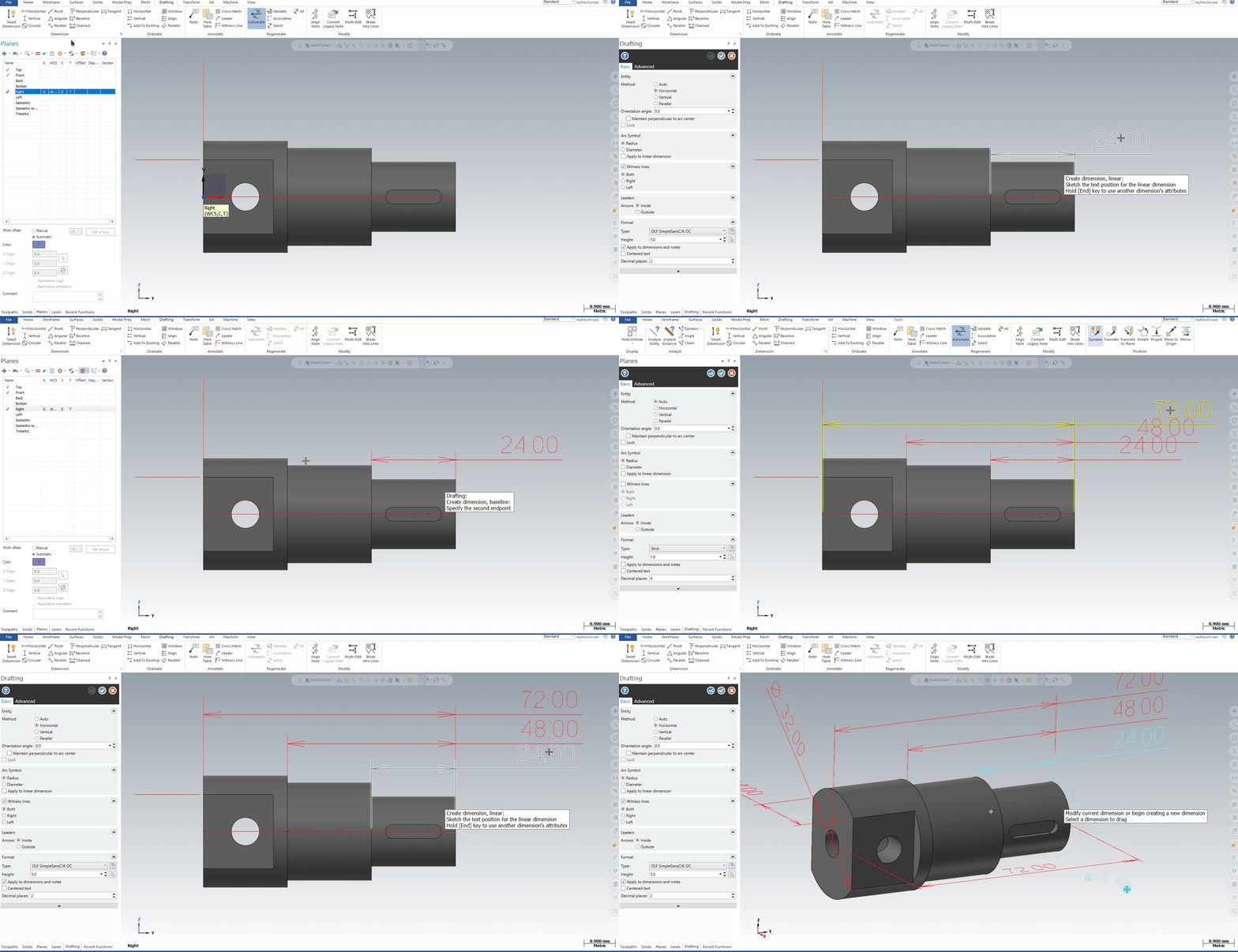
A new level is created to store the notes so that they can be hidden if necessary. The drafting tab has all the tools required to create dimensions and annotations. When creating a new entity, Mastercam will use the active level to place the note or dimension. Shown below is the difference in planes used to create a note.

Dimensioning can be done on the solid directly as long as the feature is visible from the active plane.

Creating a dimension is done by using the tools in the drafting tab and following the prompts for extra information. For example, creating a baseline dimension requires an existing dimension to work from.
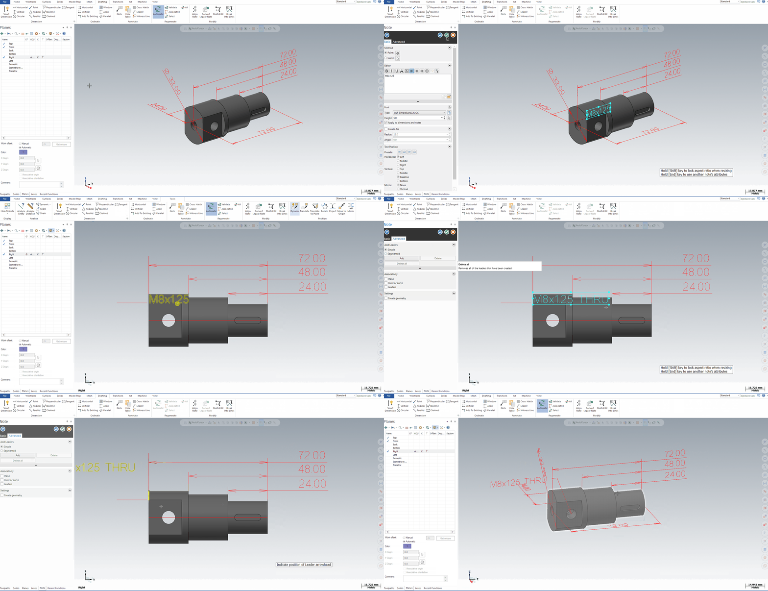
Notes can be created with or without leaders as shown below and the leaders can be linked to any wireframe or solid feature.
3D PDFs
3D Annotations, geometry, and even toolpaths can be exported to a 3D pdf using Mastercam. This gives the option to send job-specific information in an interactive file that is freely available to anyone. Mastercam will only save what is visible in the viewport when saving as a 3D PDF.
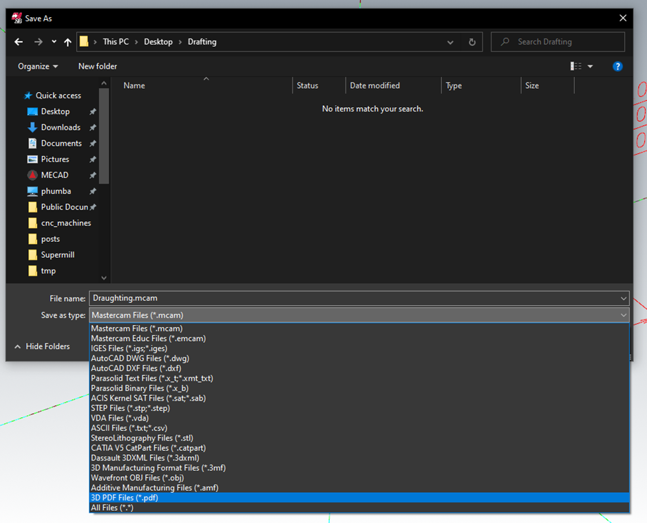
Please note that not all pdf readers support 3D PDFs. The functionality using Adobe Reader can be seen below.

Creating Technical Drawings
Under the solids tab, there is a tool called “Layout” which allows a part to be converted into a technical drawing. To use this tool effectively, the first step is to create a new viewsheet and layer to keep the drawing separate from the part.

When creating a new layout, previous drafting entities will not be transferred, only the selected solids.
Template Files are used to import drawing boarders into Mastercam. The one selected in this blog can be found HERE. The layout tool can be used to select the scale of the drawing (eg 2:1, 1:1, 1:2) to fit correctly on the template page. The new drawing can be placed on any level and the layout method can be selected for a quick automatic layout.

After selecting the green check, a new panel is shown with the drawing placed on the top plane. From this panel, the views of the part can be adjusted, with extra tools available.

Views can be added or removed if the default layout does not have the required views.

The pan and align tools can be used to move the views around on the page.

A section view can be added with the add selection tool.


On the second page, the scale of views can be adjusted.

After clicking the green check, the drawing is created. From this point dimensions, notes, and other details can be created.

The drafting tab is a useful addon that allows for notes and dimensions to be added to Mastercam files so that switching between Mastercam and other CAD software is not required. By including drafting notes in the file, sharing a project between computers only requires a single file instead of an entire design pack.
For more information contact us at 012 645 4300 or request a demo online.