Setting up a part correctly in Mastercam for a Horizontal Machining Centre (HMC) is essential for optimising workflow and ensuring machining efficiency.
This guide will walk you through the recommended best practices for part setup in Mastercam, from initial positioning to selecting the correct post processor for 3- and 4-axis HMCs.
HMCs offer a range of fixturing options, making them ideal for heavier parts that require efficient production setups.
Additionally, this blog includes a bonus tip demonstrating how to combine toolpath transforms with multi-axis linking, allowing for precise transition control between toolpaths on a 4-axis HMC.
1. Can I run VMC Code on an HMC Machine
For 3-axis machines, HMCs and Vertical Machining Centres (VMCs) function similarly.
G-code generated for a VMC should theoretically run without issues on an HMC, provided the part is positioned correctly in both setups.
The images below demonstrate this concept using Mastercam’s VMC setup and CIMCO machine simulation to visualise the G-code on an HMC.

G-code from a VMC post processor, shown on a generic VMC.

G-code from VMC post processor, shown on generic HMC.

It is clear that the G-code from a VMC post processor, shown on a generic HMC matches on both machines. Additionally, tombstone fixturing can be pre-configured if the HMC has a 4th axis.
Important to note: At this stage we have only used a generic VMC Mastercam setup and post processor.
2. Mastercam Part- and Plane- set up specifically for an HMC
For optimal results when programming an HMC in Mastercam, follow this recommended setup. This method ensures compatibility with both 3- and 4-axis machining.
Using the previous example, we now rotate the entire part and vise geometry in Mastercam to match the real-world HMC setup.
For best practice:
- Align the part’s face towards the spindle of the HMC (approaching from the front plane).
- On a VMC, the spindle comes from the top plane.
Example of an isometric plane view for an HMC setup:

The toolpath generated should match the one created in the VMC operation exactly in terms of G-code output.
Toolpath setup adjustments:
- Tool and construction planes: Set to Front Plane in toolpath parameters.
- WCS (Work Coordinate System): Remains Top Plane.

3. Selecting the Correct HMC Post Processor
Once the HMC setup is complete, the correct post processor must be used.
Options include:
- A custom-built post processor tailored to your machine.
- A generic HMC post processor, available for download from the Mastercam Tech Exchange.
🔗Download the generic HMC post processor here: Tech Exchange – Home
For assistance in selecting the correct post processor, contact MECAD Manufacturing.

4. 4th axis Fixturing technique – Tombstone Fixturing
As demonstrated earlier, the setup is already optimised for tombstone machining. This enables improved production efficiency on an HMC.
For tombstone fixturing, there are two primary options:
Option 1: Manually Add Work Offsets on the CNC Machine
Use the existing G-code and manually assign work coordinates (G55, G56, G57, etc.) to match the tombstone positions.
Option 2: Program the entire process in Mastercam
For full Mastercam automation, the recommended setup should look like this:

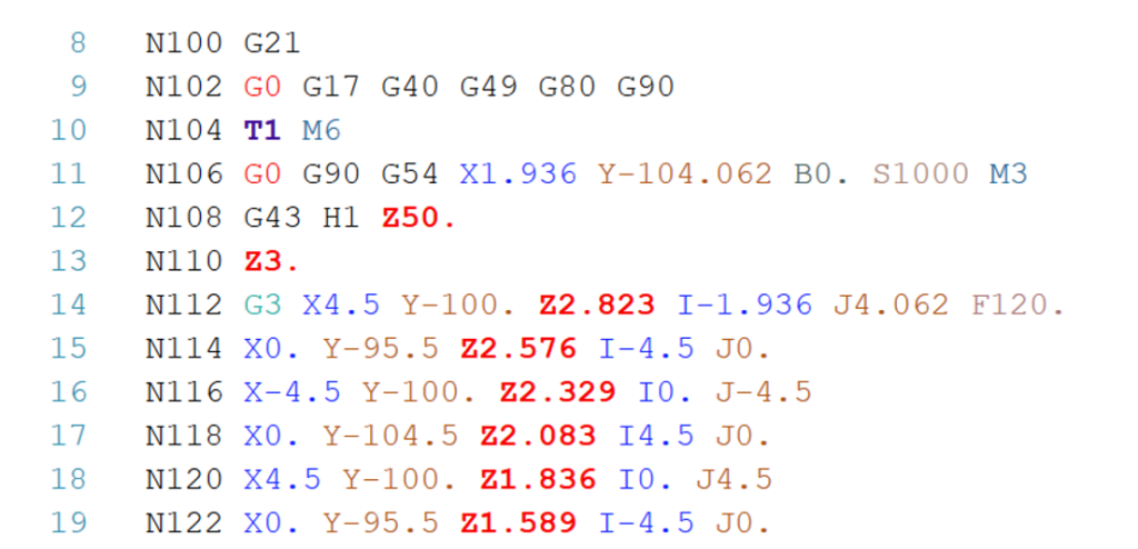
- Move the fixture centre to the WCS coordinate centre to use a single G54 work offset.
- This enables automatic B-axis rotations and simultaneous 4-axis motion.
Comparing G-code outputs from different setups:
G54 on top of part:
G54 in centre of fixture:

5. Toolpath Transform – rotating around HMC’s Y axis (B-axis)
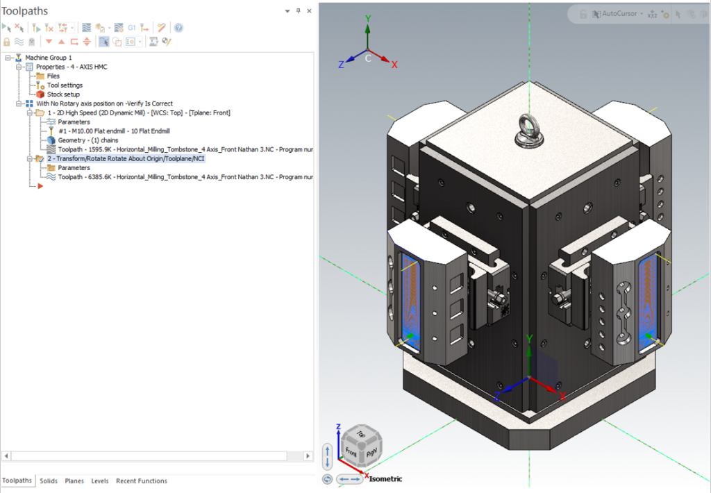
The next step in this fixturing setup is to include toolpath transformations.
To simplify programming and reduce at-machine setup time, we use toolpath transformations.
This eliminates the need for multiple manual work offsets (G55, G56, etc.), improving efficiency.
After applying a toolpath transform in Mastercam, the screen displays four toolpaths (without transition motion). Transition motion is determined by the post processor and can be visualised using CIMCO simulation.
The resulting G-code output:
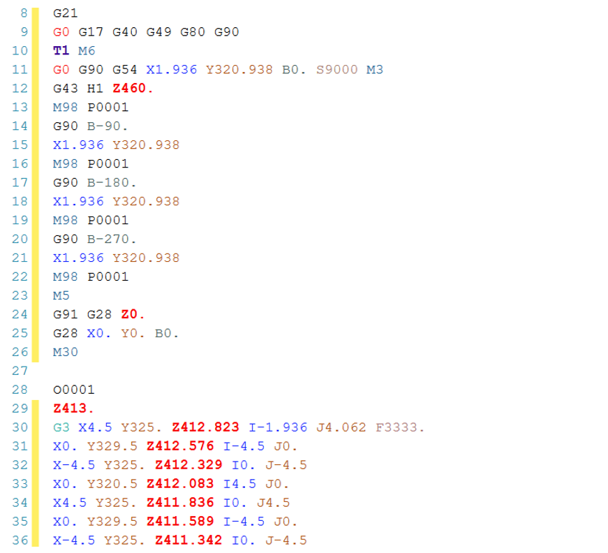
This setup ensures:
- Four B-axis rotations efficiently executed using a single sub-program.
- A post processor that correctly handles transform settings.
6. Confirm the G-Code
By importing the Mastercam setup and G-code into CIMCO machine simulation, the final toolpath and transition motion can be validated.

Watch the full G-code simulation here:
7. Bonus tip: Controlling transition motion directly from Mastercam
Mastercam allows direct transition control by applying a feed toolpath to transition movements.
By using a multi-axis link toolpath, users can ensure smooth transition motion:

CIMCO visualisation of the result:

Watch the demonstration here:
The Bottom Line
Following these best practices for Mastercam setup on an HMC will improve efficiency, streamline programming, and enhance machining accuracy. For further assistance, contact MECAD Manufacturing.